Engineering · Project management · Retrofit

Rebuilding tire extrusion lines.Planned through to ramp-up.

We plan and manage rebuilds of extruders, multiplex heads and the entire upstream and downstream chain. With 25 years of experience in tire plants, independent of the equipment manufacturer, and with our own 3D survey accurate to 0.05 mm.

Quadruplex group in piggyback arrangement · generic model Pin-barrel extruder · Cap Extruder · Wings Extruder · Base Multiplex head Take-away conveyor
Quadruplex group in piggyback arrangement · generic model

Your project manager

One point of contact for the entire rebuild.

A rebuild on a running tire line affects mechanics, process engineering, electrics, schedules and several suppliers at once. We take on project management on your side: we define what gets built, select the right suppliers together with you and support the execution until the line is producing stably again.

What we do

  1. 01Assessment and 3D survey of the equipment
  2. 02Concept, feasibility and budget range
  3. 03Specification and vendor-neutral bid comparison
  4. 04Design, interfaces and schedule
  5. 05Installation supervision within the shutdown window
  6. 06Commissioning, ramp-up and documentation

What you get

  1. →Decisions based on measured data, not assumptions
  2. →A shutdown that is planned in advance and does not run over
  3. →Recommendations that fit your line, not a catalog
  4. →Fewer interfaces for your own team, one person accountable
  5. →Up-to-date technical data on your equipment that stays with you
  6. →A ramp-up with clear targets for weight, profile and output

The heart of the line

The multiplex group, from every side.

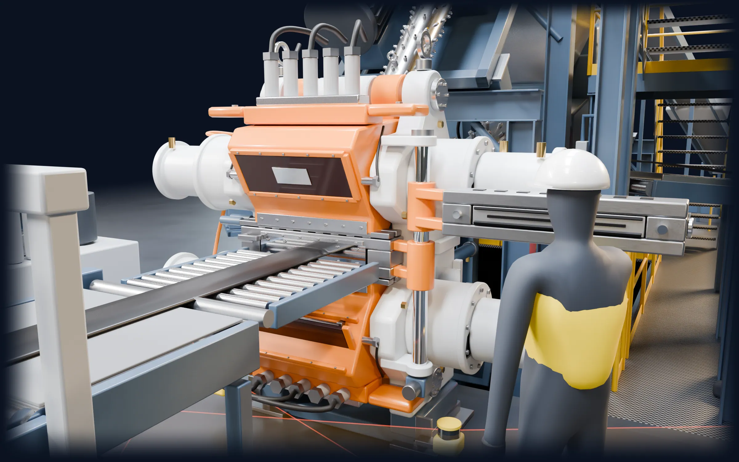
Three main extruders and a side-arm extruder feed one head. That is how a tread of five compounds is made in a single step. This group is exactly where we start with retrofits and rebuilds.

  1. Three pin-barrel extruders aligned radially on one head: cap, base and wings, plus the 45 mm side-arm extruder for the chimney. Each with its own feeding, gearbox and temperature control.

  2. The extruders sit on top of each other on supports and a platform. Short, symmetrical flow paths keep pressure and compound temperature in the window.

  3. The compounds merge inside the head. Flow channels, preformer and die plate decide on the dimensional accuracy of the tread.

  4. Cassette changer on the head housing, set-up cart with profile bars and the operator desk of the line. This is where the speed of a product change is decided.

The whole line

Ride along with the tread through the line.

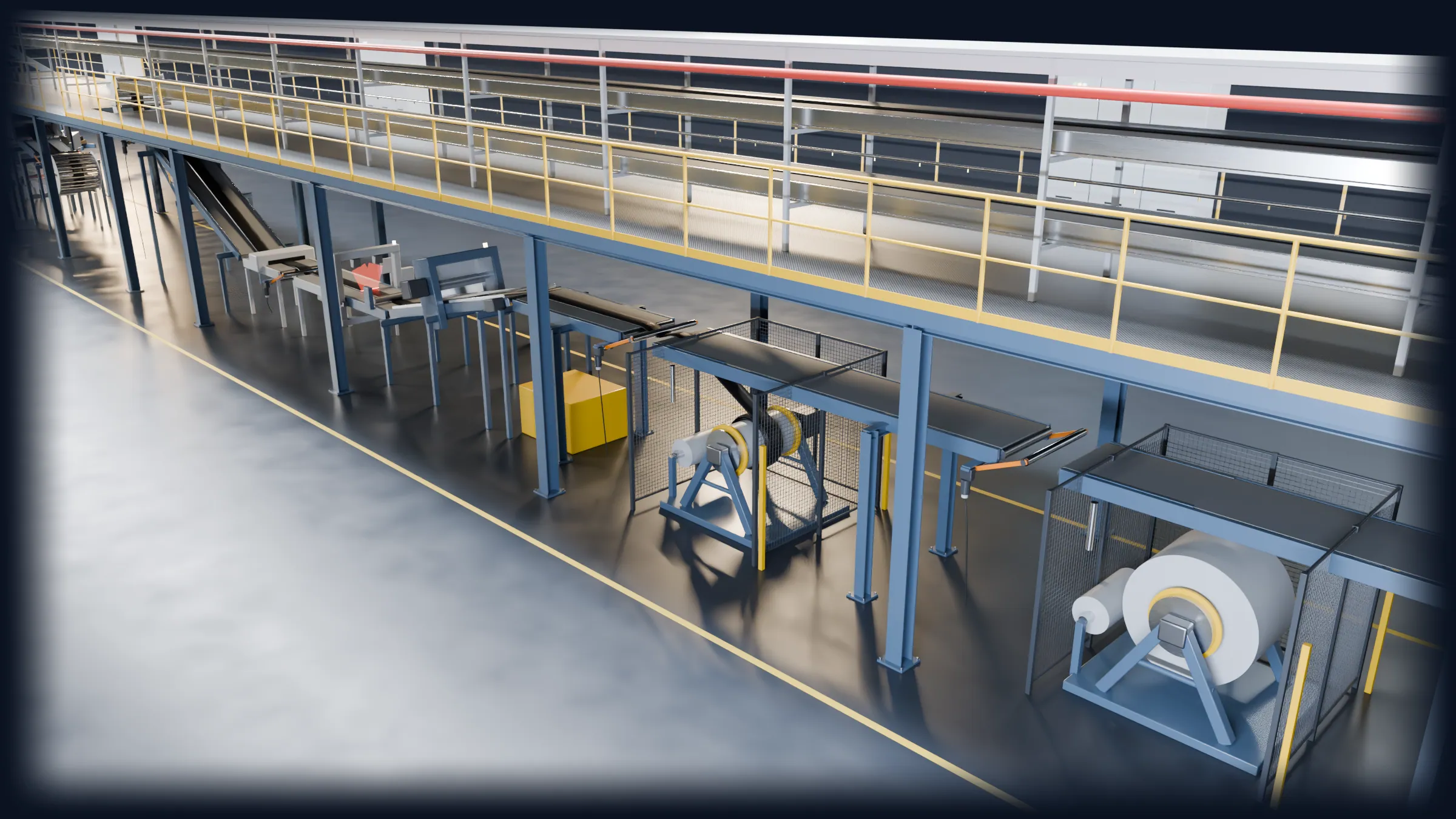
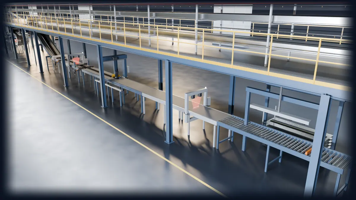
From the die to the winder or book cart: around 100 metres on which the profile shrinks, is measured, cooled and cut. Two follow-on systems, passenger car and truck.

  1. The start-up flap swings up from below to extrusion height and bridges the operator space in front of the head. The profile leaves the die at 1,200 mm.

  2. Right after the take-away the colour stripes go on. The hot profile then runs over rollers in four driven segments, getting smaller towards the end, and shrinks under control below the extraction hood.

  3. At every hand-over a dancer rests lightly on the profile. Its angle trims the next conveyor, so tension stays constant and nothing is stretched. Then weight per metre on the scale conveyor and contour, width and gauge by laser scanner.

  4. At the end of the measuring section the profile reverses: a roller basket guides it round the turn, a dancer takes over right after. The ascending conveyors with corrugated roll and liner station carry it back towards the head onto the cooling platform at 3.8 m.

  5. Up top the profile runs forward on the first cooling belt to the end of the platform and back on the second. About 100 m of spray cooling above the entire downstream.

  6. At mid-line the profile drops through an opening in the platform. The roller basket turns it, a dancer hands it to the declining conveyor back to working height.

  7. Metal detector, width measurement, scale and profile scanner release the cold, shrunk profile. The pricking roll vents the surface.

  8. A knife on a driven shaft cuts at line speed. Rejects run over the rejects conveyor into the bin.

  9. Via the transfer conveyors at 2.15 m the profile reaches the guarded winders. A dancer in front of each winder keeps the tension constant, the transfer flap opens.

  10. The profile is wound onto the cassette with a liner. When it is full, the cross-cutter cuts, the second winder takes over and the full cassette is exchanged.

  11. Thick truck treads continue without the cross-cutter. The dancer matches cooling line and skiver without stretching the profile.

  12. The carriage travels at line speed while the large disc knife makes the bevel cut for the splice on the building machine.

  13. The piece is accelerated, measured and weighed.

  14. The vacuum gripper places every good piece into the book cart, rejects are diverted.

Services

Three areas. One line.

We work on every assembly of a tire extrusion line and on existing equipment from any manufacturer.

01 · Extruders

Output and compound temperature under control.

Whether a new product, higher throughput or a drive at the end of its service life: we assess the extruder as a whole and design the intervention to match the compound and the head.

  • Size and replace drives: motor, gearbox, coupling
  • Optimize screw geometry and pin configuration
  • Match output to the product, not simply increase it
  • Adjust barrel length and temperature control zones
  • Wear measurement on screw, barrel and pins
  • Modernize temperature control units and controls

Typical case

Situation
New compound, the compound temperature is too high.
Action
Adjust pin rows and screw geometry, retune the temperature control zones.
Result
A stable process window for the new compound, without a new extruder.
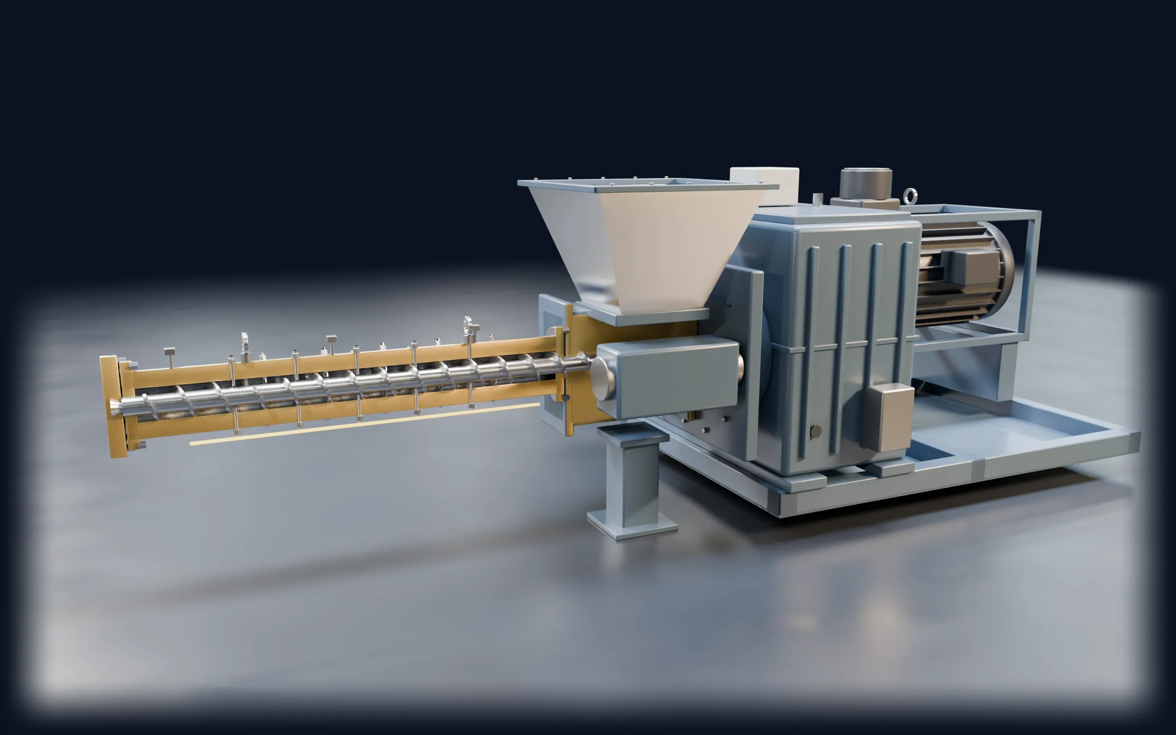
01 · Extruders 123456
  1. 1Outlet flange to the head
  2. 2Screw with interrupted flights
  3. 3Pin barrel
  4. 4Hopper and feed roll
  5. 5Gearbox
  6. 6Drive motor

02 · Extrusion heads

More components, faster changes.

The head determines profile, layer structure and changeover time. We plan extensions, new inserts and change systems for multiplex, roller-head and wide extrusion heads.

  • Extend multiplex heads, for example from triplex to quadruplex
  • Add a chimney: side-arm extruder at extrusion height or on the upper head part
  • Design and balance flow channels and preformers
  • Head inserts for new widths and component layouts
  • Speed up cassette and die changes
  • Rework locking, hydraulics and head temperature control

Typical case

Situation
A new tire type needs a conductive chimney.
Action
Side-arm extruder at extrusion height, adapted flow channel insert.
Result
The product runs on the existing line.
02 · Extrusion heads 1234
  1. 1Tooling: cassette, splice bar, final die
  2. 2Hydraulic locking
  3. 3Head bushing and extruder flange
  4. 4Cassette changer: two swing arms

From profile to tyre

How profiles become a tyre.

More than half of a tyre comes out of an extruder: tread, sidewall, apex and innerliner. On the left the tread as it leaves the multiplex head, on the right its place in the finished tyre.

01Tread from the headFive compounds joined into one profile in a single step.
w Cap · running surface Chimney · conductive Wings · shoulder Base · undertread Cushion · bonding layer
02Building the tyre
01

Extruded, on lines like the ones we retrofitCalendered or wire

Simplified, cured half section without tread grooves. Dimensions plausible, not tyre-specific.

03 · Upstream & downstream

The line around the extruder.

An extruder is only as good as the line around it. We look at the process chain from strip feeding to the book cart or winder.

Cooling platform, cross-cutter and winders (PCR)
Skiver, length check and book cart (TBR)
  1. 01

    Feeding

    Strip feeding, strip festoon, metal detection, cold feed instead of hot feed.

  2. 02

    Take-away and shrinkage

    Take-away conveyor, shrinkage roller conveyor, strip tension and dancer control.

  3. 03

    Measurement and control

    Profile, width, weight per meter, control loops for take-away and screw speed.

  4. 04

    Cooling

    Spray, immersion and drum cooling, multi-tier, including water systems.

  5. 05

    Cutting and handling

    Skiver, cross cutter, booking and wind-up with liner.

  6. 06

    Quality

    Marking, reject handling, traceability and rework.

Typical case

Situation
The line needs to run faster, but the profile reaches the skiver too warm.
Action
Extend the cooling line, rework the spray pattern and water circuit.
Result
Higher line speed with stable length.

How a retrofit runs

A new extruder at the bottom of the head. Step by step.

The most demanding case: the base extruder grows from 120 to 150 mm. To get there, the upper extruders have to come out. The simulation shows the sequence we plan together with your team.

  1. Production stops, the profile runs out into the winder or book cart.

  2. The operator opens the wedge comb and folds the cassette with splice bar and profile bar out on its hinge to the operator side.

  3. The upper head part swings up, the lower part swings down.

  4. The inserts travel forward on the rods of the hydraulic cylinders. The mobile crane lifts them onto pallets with chain slings on the eye bolts.

  5. The shrinkage conveyor moves aside. Each screw then comes out forward through the open head and is laid on trestles.

  6. The feeder conveyors are dismantled and moved away so the crane has free access above the extruders.

  7. The mobile crane lifts out the wing and cap extruders with their portals. Only then is the base extruder free.

  8. Release the flange, pull back axially, lift out.

  9. The old bushing is unscrewed, the new one for 150 mm is screwed in.

  10. The new extruder (new parts in gold) is lifted in, moved onto the bushing, aligned and bolted.

  11. Portals, cap and wing extruders, feeders and screws go back.

  12. The new lower insert (gold contour) and the upper insert go onto the rods and retract into the head. Close and lock the head.

  13. The operator folds the cassette in front of the mouth, the wedge comb clamps, the start-up flap swings up. He guides the first profile onto the take-away.

Generic representation, based on real retrofits. Durations and lifting gear are defined per project.

Project process

Measure first, then plan, then rebuild.

Every project follows the same logic. In every phase you know what has been decided, what it costs and what comes next.

  1. 01

    Assessment

    We record the condition, interfaces and data of your line, by 3D scan where needed.

    ResultCondition report, 3D data, bottleneck analysis

  2. 02

    Concept

    We evaluate options technically and economically.

    ResultFeasibility study, layout, budget range

  3. 03

    Specification and award

    We write the specification and compare bids on a vendor-neutral basis.

    ResultSpecification, bid comparison, award recommendation

  4. 04

    Execution

    We coordinate suppliers, installation and schedules within the agreed shutdown window.

    ResultSchedule, installation supervision, acceptance reports

  5. 05

    Ramp-up

    We support commissioning until weight, profile and output are stable.

    ResultRamp-up report, documentation, handover

Your team and your suppliers carry out the physical work. We lead the project technically, check every step and make sure schedules and quality are met.

3D survey · Digital twin

When drawings are missing, we measure.

Many lines have been running for decades, but their documentation has not. We scan components, heads and entire line sections on site and turn them into dimensionally accurate CAD models as the basis for design, clash detection and spare parts.

  • 3D scan from single part to line layout
  • CAD reconstruction, not just a point cloud
  • Clash detection for new components
  • Spare parts without original drawings

up to 0.05 mmAccuracy of the on-site survey

Worldwide

We work where tires are built.

Tire plants are located in Europe, the Americas and Asia. We work with all tire manufacturers, on equipment of every make, and we speak German, English and Spanish. We do not name customers. References are available on request.

Tire production centers
  • 01

    Europe

    Central, Eastern and Southern Europe

  • 02

    North America

    USA and Mexico

  • 03

    South America

    Brazil and neighboring countries

  • 04

    Asia

    China, India, Southeast Asia

Why Hercules

We speak your line's language.

  1. 01

    Vendor-neutral

    We recommend what fits your line, not what a catalog offers.

  2. 02

    The entire line

    Extruder, head, upstream and downstream in one assessment.

  3. 03

    From the shop floor

    25 years in tire plants: production, development and rebuilds.

  4. 04

    Predictable shutdowns

    Measure and plan before the first intervention, rebuild within the agreed window.

  5. 05

    Our own 3D data

    Survey accurate to 0.05 mm, even where drawings are missing.

  6. 06

    Three languages

    German, English and Spanish, directly with plant, supplier and installation crew.

FAQ

What a rebuild on a running line involves.

Does Hercules carry out the rebuild itself?

We plan, engineer and lead. We handle assessment, design, measurement and optimization ourselves. The physical work is carried out by your staff and your suppliers. We provide supervision, coordinate the interfaces and make sure schedule and quality are met.

Does the make of our equipment matter?

No. We are not tied to any make and work on existing equipment from every manufacturer, from the extruder and head to the peripherals. Where design documents are missing, the 3D survey provides the data basis.

How does the shutdown stay predictable?

Before the first intervention, we record the existing equipment precisely and plan the rebuild in detail, including pre-assembly and spare parts. The work takes place within an agreed shutdown window. This keeps the downtime calculable.

Do you also work internationally?

Yes. Tire plants are located worldwide, and we work where the line is. The project language is German, English or Spanish.

How does a project start?

With a conversation about your equipment and your goal. If it makes sense, an on-site assessment follows. After that you know what is technically possible, how long it will take and what the cost range is.

Contact

Let's talk about your line.

Briefly describe your equipment and your goal. We will get back to you personally.

Your contact

Raymond Jöhnk

Managing Director, Hercules GmbH

Tel. / WhatsApp
+49 162 3223301
Address
Nenndorfer Str. 85i · 30952 Ronnenberg · Deutschland

Prepare your inquiry

Topic

The inquiry opens your email program. No data is stored on this website.